Customizable Pad Mounted Transformer: Engineering Flexibility Into Power Distribution Networks
Power distribution networks rarely follow a standard blueprint. A coastal industrial park faces salt-laden air that corrodes exposed metal within months. A residential development sits on unstable soil that shifts with seasonal rainfall. A data center requires voltage regulation tighter than what off-the-shelf equipment can deliver. These scenarios share a common limitation: pre-configured equipment often forces compromises that ripple through operational efficiency and long-term reliability.
Customizable pad mounted transformers address this challenge by treating enclosure design, thermal management, and internal architecture as variables rather than fixed parameters. Unlike standard units that assume uniform environmental conditions and load patterns, these systems begin with a site assessment and end with a transformer whose physical form and electrical characteristics align with actual field requirements.
Why Standard Configurations Fall Short in Complex Installations
Standard pad mounted transformers follow industry-wide dimensional and performance templates. This uniformity simplifies procurement and installation, but it creates friction when site conditions deviate from assumed norms. A transformer rated for ambient temperatures up to 40°C may throttle output during summer peaks in desert climates. Enclosures designed for moderate humidity can trap condensation in tropical regions, accelerating insulation degradation.
Load profiles add another layer of complexity. A manufacturing facility with motor-driven equipment generates harmonic currents that overheat windings sized only for linear loads. A mixed-use development with residential and commercial tenants experiences sharp demand spikes that standard cooling systems struggle to dissipate. These mismatches don't always cause immediate failure, but they erode transformer lifespan and force expensive mid-cycle replacements.
Customization resolves these gaps by treating each installation as a distinct engineering problem. Enclosure materials shift from painted carbon steel to stainless alloys in corrosive environments. Winding configurations adjust to handle expected harmonic distortion. Cooling fins extend surface area when ambient temperatures regularly exceed design limits. The result is a transformer whose operational envelope matches the stresses it will actually encounter.
Core Elements That Define a Customizable System
A customizable pad mounted transformer operates as an integrated system where the enclosure, internal components, and thermal management work as interdependent subsystems. The enclosure does more than shield components from weather; it acts as the first line of defense against tampering, dust infiltration, and mechanical impact. Sealed designs with gasket-reinforced doors prevent moisture ingress in high-humidity zones. Tamper-resistant locks and reinforced panels deter unauthorized access in urban installations where vandalism poses real risk.
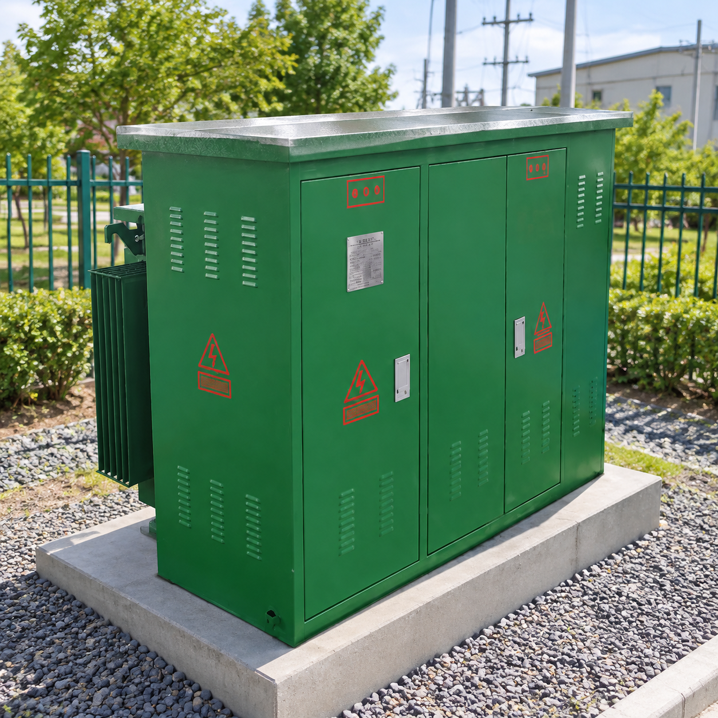
Internal architecture varies with operational requirements. High-voltage switching units integrate directly into the enclosure, eliminating the need for separate disconnect equipment. Low-voltage distribution panels consolidate metering, protection, and circuit routing into a single access point. This consolidation reduces footprint and simplifies maintenance, but it demands precise coordination between transformer ratings, breaker capacities, and expected fault currents.
Thermal management separates adequate designs from robust ones. Ambient temperature, solar radiation, and internal losses all contribute to operating temperature. Standard cooling relies on natural convection through fixed ventilation louvers. Custom systems add external radiators, forced-air ventilation, or heat exchangers when load density or climate pushes beyond passive limits. The choice depends on lifecycle cost calculations that weigh upfront complexity against reduced derating and extended insulation life.
Material Selection and Environmental Durability
Enclosure materials directly influence longevity in harsh environments. Painted carbon steel suffices in temperate climates with low pollution, but corrosion accelerates near coastlines, chemical plants, or areas with high sulfur dioxide concentrations. Stainless steel or aluminum alloys resist oxidation but increase material cost. The tradeoff becomes an economic calculation: higher upfront expense versus the cost of premature enclosure replacement and associated downtime.
Powder coating provides a durable finish that resists UV degradation and impact damage better than liquid paint. The electrostatic application process creates a uniform layer that adheres tightly to metal surfaces, reducing the risk of chipping that exposes bare metal to moisture. Color selection also matters; lighter shades reflect solar radiation and reduce internal temperature rise in exposed installations, while darker colors may better match architectural requirements in urban settings.
Gasket materials and sealing methods determine how effectively the enclosure blocks dust and moisture. Silicone or EPDM rubber gaskets maintain flexibility across wide temperature ranges, but they require compression to form effective seals. Bolted door designs with adjustable latches allow field personnel to restore sealing pressure as gaskets age. Hinge placement and door alignment affect how evenly sealing force distributes around the perimeter.
Internal Configuration: Balancing Protection and Accessibility
High-voltage compartments house disconnect switches, fuses, and surge arresters. Customizable designs adjust component spacing based on voltage class and fault current ratings. Ceramic insulators separate live conductors from grounded enclosure walls, with arc distances calculated to prevent flashover during transient overvoltages. Cable entry points use heat-shrink boots or cold-shrink insulators to maintain electrical clearance where conductors penetrate metal walls.
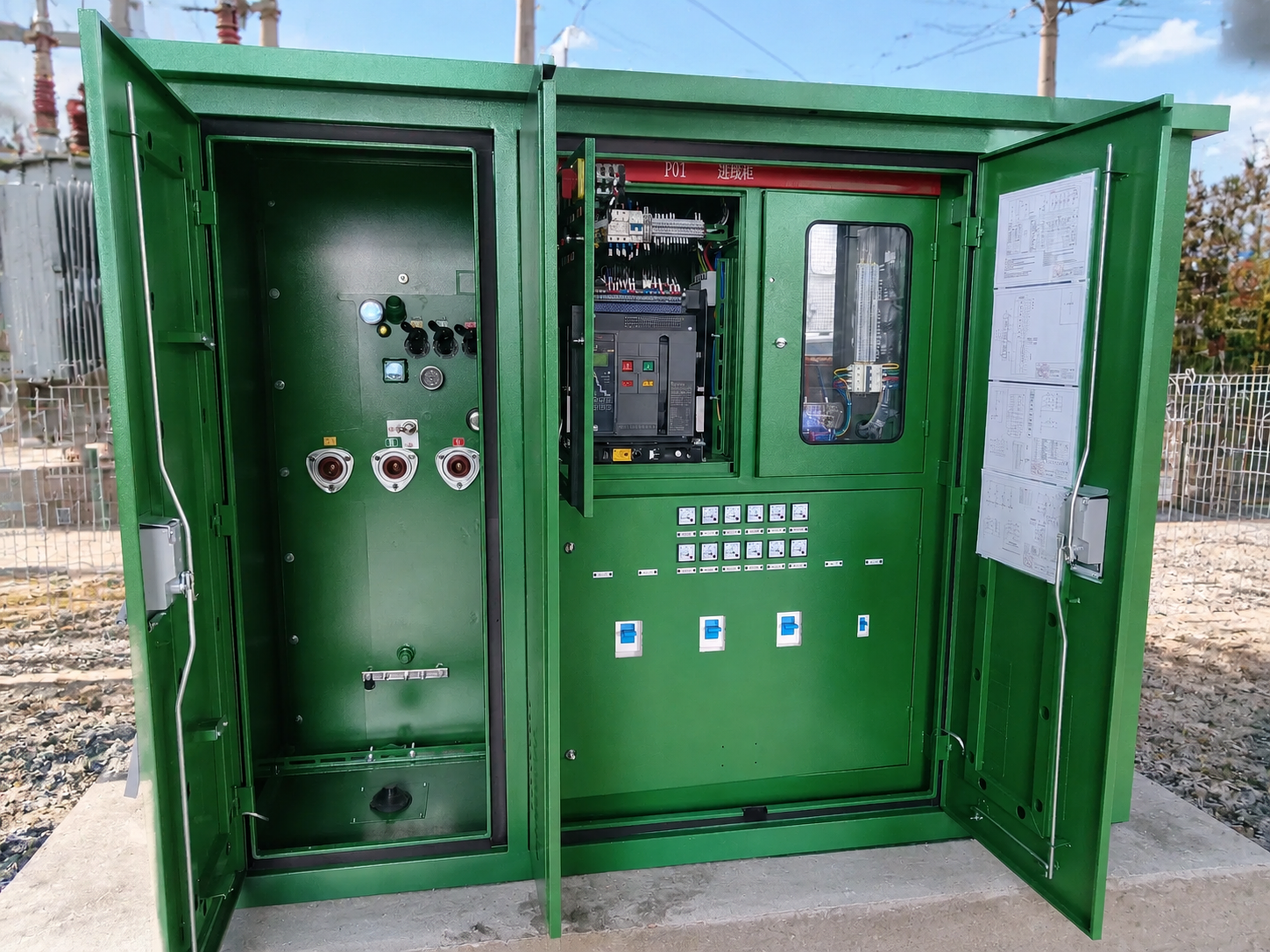
Low-voltage distribution systems integrate metering, overcurrent protection, and load switching into a single panel. Analog or digital meters display voltage, current, power factor, and energy consumption. Main breakers with adjustable trip settings protect downstream circuits from overloads and short circuits. Capacitor banks correct power factor when inductive loads dominate, reducing reactive power demand and associated utility penalties.
Component layout affects both safety and maintenance efficiency. Separating high-voltage and low-voltage compartments with grounded barriers reduces shock risk during service. Color-coded wiring and labeled terminal blocks speed troubleshooting. Removable panels provide access to connections without fully de-energizing the system, though this requires strict lockout-tagout procedures to prevent arc flash injuries.
Voltage Regulation and Harmonic Mitigation
Non-linear loads—variable frequency drives, switched-mode power supplies, LED lighting—inject harmonic currents back into the distribution network. These currents distort voltage waveforms and overheat transformer windings and neutral conductors. Standard transformers with conventional windings may derate when serving loads with high total harmonic distortion (THD).
Custom winding designs mitigate harmonic heating. K-rated transformers feature oversized neutrals and conductors rated to handle triplen harmonics (3rd, 9th, 15th) without excessive temperature rise. Phase-shifting configurations cancel specific harmonic orders by introducing controlled phase displacement between primary and secondary windings. Zigzag grounding transformers provide low-impedance paths for zero-sequence currents, stabilizing neutral voltage in unbalanced systems.
Tap changers adjust secondary voltage to compensate for varying primary voltage or load conditions. Manual tap changers require de-energization and physical adjustment, suitable for installations with infrequent voltage variations. On-load tap changers switch taps under full load using diverter switches that temporarily insert impedance during transitions. The added complexity increases cost and maintenance requirements but enables real-time voltage regulation in networks with unstable supply or critical load voltage tolerances.
| Feature | Standard Transformer | Customizable Transformer |
|---|---|---|
| Enclosure Material | Painted carbon steel | Selectable alloys (stainless, aluminum) |
| Cooling Method | Passive ventilation | Passive or active (radiators, fans) |
| Harmonic Handling | Standard winding | K-rated or phase-shifting winding |
| Voltage Regulation | Fixed taps | Manual or on-load tap changers |
| Sealing | Basic gaskets | Reinforced sealing for harsh environments |
| Internal Layout | Fixed configuration | Modular high/low voltage compartments |
Site-Specific Engineering: From Assessment to Commissioning
Customization begins with a detailed site assessment. Engineers evaluate ambient temperature ranges, humidity levels, altitude, seismic activity, and soil bearing capacity. Electrical parameters include primary voltage, secondary voltage, load characteristics (resistive, inductive, non-linear), fault current availability, and expected load growth over the transformer's lifespan. This data drives decisions about core size, winding material, cooling capacity, and protection coordination.
Thermal modeling predicts operating temperatures under worst-case conditions. Software tools simulate solar heat gain, internal losses, and ambient temperature to estimate hot-spot temperatures in windings. If predicted temperatures exceed insulation limits, engineers specify enhanced cooling, lower load density, or upgraded insulation materials. The goal is to keep operating temperatures within ranges that maximize insulation life expectancy.
Short-circuit withstand capability ensures the transformer survives fault conditions without mechanical or thermal damage. Winding bracing, conductor clamping, and core bolt tension all influence mechanical strength. Custom designs specify these parameters based on calculated fault currents, ensuring the transformer can withstand electromagnetic forces during three-phase and line-to-ground faults. Protection devices—fuses, circuit breakers, differential relays—coordinate to isolate faults before damage occurs.
Installation Considerations for Pad Mounted Units
Pad mounted transformers sit on reinforced concrete pads designed to support the unit's weight and resist settling. Pad dimensions exceed the transformer footprint to provide stable footing and prevent tipping during seismic events or accidental impacts. Anchor bolts secure the enclosure to the pad, with embedment depth and bolt diameter calculated based on wind loads and seismic design categories for the installation region.
Cable entry trenches route underground conductors to the transformer without sharp bends that stress insulation. Elbow connectors at cable terminations allow hot-line maintenance—technicians can disconnect cables using insulated tools while the primary remains energized. This capability reduces outage duration during maintenance or emergency repairs. Proper cable sizing accounts for continuous current, short-circuit current, voltage drop, and ambient temperature correction factors.
Clearance requirements ensure safe operation and maintenance access. Electrical codes specify minimum distances from buildings, property lines, and other equipment. Front clearances allow door operation and provide working space for personnel. Side and rear clearances facilitate heat dissipation and prevent vegetation from blocking ventilation. Fencing or bollards protect the transformer from vehicle impacts in parking areas or industrial yards.
Maintenance and Lifecycle Management
Scheduled maintenance extends transformer life and prevents unexpected failures. Visual inspections check for enclosure corrosion, gasket deterioration, loose connections, and signs of overheating. Thermographic imaging identifies hot spots caused by poor connections or imbalanced loading. For liquid-filled transformers, oil sampling detects dissolved gases that indicate internal faults—arcing, overheating, or insulation breakdown.
Partial discharge testing identifies insulation weaknesses before they cause failures. High-frequency sensors detect corona and surface discharges that erode solid insulation over time. Trending these measurements over years reveals degradation patterns that guide replacement decisions. Load monitoring tracks actual demand versus rated capacity, identifying transformers operating near limits that may require upsizing or load redistribution.
Spare parts availability influences long-term maintenance costs. Custom designs that use proprietary components risk parts obsolescence if manufacturers discontinue models. Specifying standard bushings, tap changers, and protection devices ensures replacements remain available throughout the transformer's service life. Documentation—electrical schematics, maintenance logs, test reports—preserves institutional knowledge as personnel change.
Economic Considerations: Total Cost of Ownership
Initial purchase price represents only one component of total cost. A customizable pad mounted transformer may cost more than a standard equivalent, but this premium buys targeted performance that reduces operating expenses. Reduced losses lower energy costs; efficiency improvements save money annually in large installations. Extended lifespan defers capital replacement costs and associated downtime.
Avoided downtime justifies higher upfront costs in critical applications. A pharmaceutical manufacturing plant that loses substantial revenue per hour during power outages cannot tolerate transformer failures caused by inadequate environmental protection. A data center with strict uptime requirements justifies redundant cooling and enhanced fault tolerance. Calculating the cost of a single unplanned outage against the incremental cost of a robust custom design often tips the analysis toward customization.
Utility incentive programs sometimes offset customization costs. Energy efficiency rebates reward low-loss transformers that reduce peak demand. Demand response programs compensate customers who install equipment with fast voltage regulation or load-shedding capabilities. Regional variations in these programs mean that economic viability depends on local utility policies and rate structures.
Integrating Advanced Monitoring and Communication
Digital monitoring systems transform pad mounted transformers from passive components into network-visible assets. Sensors measure voltage, current, power factor, temperature, and moisture ingress. Data loggers store time-series measurements for trend analysis. Communication modules transmit data via cellular, fiber, or mesh radio networks to centralized SCADA systems.
Fault detection algorithms process real-time measurements to identify abnormal conditions. Sudden temperature spikes indicate overloads or cooling failures. Voltage imbalances suggest winding faults or unbalanced loading. Moisture ingress triggers alarms before condensation degrades insulation. Early detection enables preemptive maintenance that prevents catastrophic failures and extends equipment life.
Predictive maintenance models use historical data and machine learning to forecast remaining useful life. Algorithms correlate operating temperature, load cycles, and ambient conditions with known failure modes. Maintenance teams prioritize inspections and replacements based on predicted failure probability, optimizing resource allocation across large transformer fleets. This shift from time-based to condition-based maintenance reduces both maintenance costs and unexpected failures.
For us at FORUI, with over 18 years of experience in transformer manufacturing, the shift toward customizable pad mounted transformer solutions reflects how power distribution demands have evolved beyond one-size-fits-all approaches. Each project brings unique environmental and electrical challenges that require thoughtful engineering rather than catalog selection.
Selecting the Right Customization Strategy
Not every installation requires full customization. A suburban residential development with moderate climate and predictable loads may perform adequately with a near-standard transformer that incorporates minor adjustments—upgraded enclosure coating, slightly oversized cooling, enhanced gasket sealing. The customization spectrum ranges from these incremental modifications to fully bespoke designs with unique voltage ratios, harmonic filters, and active cooling systems.
Decision criteria include environmental severity, load criticality, expected lifespan, and budget constraints. Harsh environments—coastal, industrial, extreme temperatures—justify substantial enclosure and cooling customization. Critical loads—hospitals, data centers, water treatment—demand redundant protection and monitoring. Long planning horizons favor investments in durability and efficiency that pay back over decades.
Vendor capabilities matter as much as technical specifications. Manufacturers with in-house engineering, testing facilities, and flexible production lines can accommodate custom requirements more effectively than those relying on outsourced components and rigid manufacturing processes. References from similar installations provide evidence of successful customization execution and long-term support.
Field Performance and Continuous Improvement
Operational data from installed customizable pad mounted transformers informs future designs. Load patterns, environmental conditions, and maintenance history reveal which customizations deliver measurable benefits and which add cost without proportional value. Manufacturers who systematically collect and analyze field data refine their engineering models and improve reliability predictions.
Failure analysis identifies root causes when equipment underperforms. Metallurgical examination of corroded enclosures reveals whether coating specifications adequately resisted site conditions. Thermal imaging during post-failure inspections shows whether cooling capacity matched actual thermal loads. Electrical testing determines if insulation strength met design expectations. These investigations close the feedback loop between field performance and design assumptions.
Standards evolution incorporates lessons from field experience. Industry committees update insulation requirements, short-circuit ratings, and environmental testing protocols based on documented failures and emerging technologies. Manufacturers who participate in standards development shape future requirements and ensure their designs remain compliant as codes evolve.
Customizable pad mounted transformers represent a pragmatic response to the reality that power distribution occurs in environments too varied for standardized solutions to universally succeed. The engineering effort required to match transformer characteristics to site conditions pays dividends through reduced failures, lower operating costs, and extended equipment life. As electrical loads grow more complex and environmental conditions more challenging, the value of this tailored approach only increases.
Recent Posts
- FORUI Makes a Strong Appearance at ENERGETAB Poland 2025, Deepening European Market Presence
- FORUI Presents at Uzbekistan Energy Week 2025, Contributing to Central Asia's Energy Development
- FORUI Shines at Electrical Networks of Russia 2024, Showcasing Strength of Intelligent Manufacturing
- Power Transformer Basics: How Oil-Immersed Units Keep the Grid Running
- Compact Substation: Engineering Precision in Modular Power Distribution
SUBSCRIBE
INQUIRY