Oil Immersed Transformer: Engineering Foundations and Selection Logic
When power infrastructure demands consistent voltage regulation across changing loads, the choice of transformation technology becomes a structural decision rather than a procurement detail. Oil immersed transformers remain a dominant solution in utility networks, industrial facilities, and renewable energy installations—not because of tradition, but because liquid insulation physics offer thermal and dielectric advantages that alternative designs struggle to match at scale.
This article examines the operational principles, design trade-offs, and application contexts where oil-cooled technology delivers measurable performance. Understanding these factors helps engineers and project planners identify when this architecture aligns with their system requirements.
How Liquid Insulation Changes Heat Management
The core advantage of an oil immersed transformer lies in its dual-function cooling medium. Insulating oil circulates through the windings and core, simultaneously preventing electrical breakdown and transferring heat to external radiators. This convection-driven process handles higher power densities than air-cooled equivalents of similar footprint.
Heat dissipation efficiency directly impacts transformer lifespan. When winding temperatures rise beyond design thresholds, insulation degradation accelerates. Oil circulation maintains temperature gradients within acceptable ranges even during peak demand cycles, which extends operational life in continuous-duty applications.
The thermal capacity of mineral oil also provides short-term overload tolerance. During transient surges, the oil absorbs excess heat before reaching critical winding temperatures. This buffer allows brief capacity exceedances without triggering protective shutdowns—a characteristic particularly relevant in renewable energy systems where output fluctuates with weather conditions.
Construction Principles and Material Choices
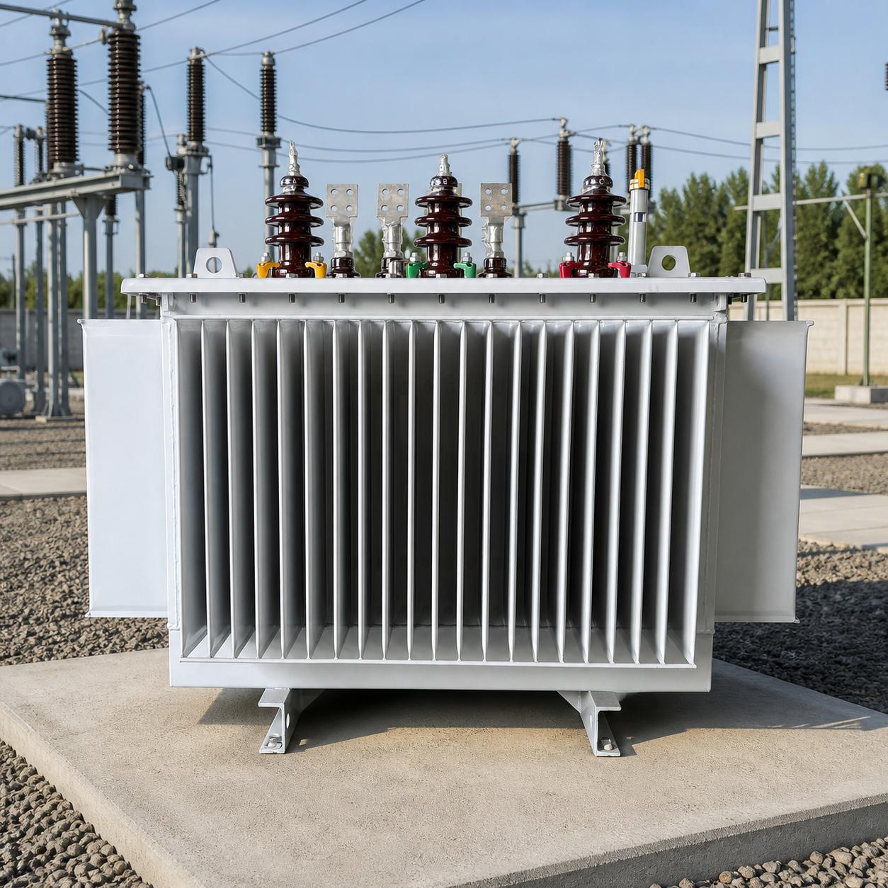
Modern oil-filled units integrate several engineering subsystems. The transformer core consists of laminated silicon steel sheets, reducing eddy current losses. Copper or aluminum windings wrap around the core in precise geometries that balance impedance, fault tolerance, and manufacturing cost.
The tank enclosure serves multiple roles: it contains the oil volume, provides structural support, and acts as a mounting surface for external components. Steel tanks undergo anti-corrosion treatment and pressure testing before final assembly. Radiator fins or separate cooling banks attach to the tank walls, increasing surface area for heat exchange with ambient air.
An expansion tank or conservator sits above the main tank, accommodating oil volume changes as temperature varies. This prevents pressure buildup and limits oil exposure to atmospheric moisture. Some designs include silica gel breathers to filter incoming air during contraction cycles.
Bushing insulators penetrate the tank lid, providing electrical connections while maintaining oil seal integrity. These ceramic or polymer components must withstand mechanical stress, electrical fields, and environmental exposure simultaneously.
Voltage Regulation Under Variable Loading
Transformers do not simply scale voltage through turns ratio. Real-world performance involves impedance drops, reactive power management, and harmonic distortion. Oil immersed designs typically exhibit lower impedance than dry-type equivalents, which improves voltage regulation under fluctuating loads.
When load current increases, impedance drop causes secondary voltage to sag. Lower impedance minimizes this effect, keeping delivered voltage closer to rated values. This matters in industrial settings where motor startups, welding equipment, or induction furnaces create sudden load steps.
However, low impedance also means higher fault currents during short circuits. The mechanical forces on windings scale with current squared, so robust bracing and clamping structures become critical. Engineers balance regulation performance against fault withstand capability when specifying impedance ranges.
Tap changers offer another regulation tool. Off-load tap changers require de-energization before adjustment, suitable for seasonal voltage shifts. On-load tap changers switch taps under operating current, compensating for daily or hourly variations. This active regulation maintains tighter voltage control in distribution networks with distributed generation.
Loss Characteristics and Efficiency Metrics
Transformer losses split into two categories: no-load losses and load losses. No-load losses occur continuously whenever the unit is energized, driven by core magnetization and eddy currents. Load losses vary with throughput, stemming from resistive heating in windings and stray magnetic fields.
Core design directly influences no-load loss. Grain-oriented silicon steel with low hysteresis reduces magnetization energy. Thinner laminations minimize eddy currents. Step-lap or mitered core joints improve flux distribution, further cutting losses. These refinements increase material and manufacturing costs but pay back through reduced lifetime energy consumption.
Load losses depend on conductor material and winding geometry. Copper offers lower resistivity than aluminum, reducing I²R heating but adding weight and cost. Optimized winding arrangements minimize stray flux, which otherwise induces losses in structural components and tank walls.
For units operating near rated capacity most of the time, load loss optimization takes priority. In lightly loaded applications—common in distribution transformers—no-load loss dominates total energy waste. Site-specific duty cycles determine which loss component merits greater attention during design.
Dielectric Strength and Insulation Coordination
Electrical breakdown occurs when field stress exceeds insulation capability. Oil possesses higher dielectric strength than air, allowing tighter spacing between conductors and grounded structures. This compactness becomes essential in high-voltage applications where clearance distances would otherwise become prohibitive.
Insulating oil also self-heals after minor partial discharges. Small arcs create localized gas bubbles that dissipate without permanent damage. Solid insulation materials accumulate defects over time, forming conductive pathways. This self-healing property contributes to the long service life observed in properly maintained oil-filled units.
Contamination degrades dielectric performance. Moisture absorption, particulate intrusion, and thermal degradation byproducts all reduce breakdown voltage. Regular oil testing monitors dissolved gas content, acidity, and moisture levels. Trending these parameters flags developing faults before insulation failure occurs.
Surge arresters and coordinated insulation design protect against transient overvoltages. Lightning strikes, switching operations, and fault clearing events generate voltage spikes that can punch through weakened insulation. Proper grounding, surge protection placement, and impulse withstand testing ensure the transformer survives these events.
Application Contexts and System Integration
Power generation facilities use step-up oil immersed transformers to raise generator voltage to transmission levels. These units handle massive power flows and must operate continuously under varying load. The thermal inertia of large oil volumes smooths temperature swings during load cycling.
Distribution networks employ step-down transformers to reduce transmission voltage for local delivery. These units often sit on concrete pads or poles, exposed to weather extremes. Sealed-tank designs with conservator systems prevent moisture ingress in humid or coastal environments.
Industrial plants require transformers that tolerate non-linear loads, harmonic distortion, and frequent startups. K-factor rated units incorporate design features that handle harmonic heating. Oil cooling manages the elevated thermal stress these operating conditions create.
Renewable energy projects face unique challenges. Wind farms and solar installations generate power at variable rates, creating bidirectional power flow and voltage fluctuations. Transformers in these systems need robust thermal management during peak generation and must maintain efficiency during partial-load operation common in off-peak periods.
Maintenance Practices and Lifecycle Management
Routine oil sampling forms the foundation of condition monitoring. Dissolved gas analysis detects incipient faults: arcing produces acetylene, overheating generates ethylene, and partial discharge releases hydrogen. Trending gas concentrations reveals degradation rates, guiding intervention timing.
Thermographic surveys identify hot spots indicating poor connections, overloading, or cooling system blockages. Infrared imaging captures temperature distributions across tank surfaces and bushing assemblies. Anomalies warrant further investigation before progressing to failure.
Bushing condition assessment combines power factor testing and visual inspection. Power factor increases signal insulation deterioration. Surface cracks, oil leaks, or tracking marks on porcelain insulators indicate imminent failure risk. Replacing bushings before catastrophic failure prevents collateral damage to internal components.
Oil filtration and regeneration extend service life. Portable filtration units remove moisture and particulates, restoring dielectric strength. Chemical treatments neutralize acidic compounds formed by thermal aging. These interventions cost less than replacement and delay end-of-life.
Load monitoring informs thermal management. Continuous tracking of loading patterns reveals overload frequency and duration. This data supports decisions about capacity upgrades, load shedding, or parallel operation. Operating within thermal limits preserves winding insulation, the component most susceptible to heat damage.
Selection Framework for Project Planners
Capacity rating must align with present load plus growth margin. Undersizing forces operation near thermal limits, shortening lifespan. Oversizing wastes capital and increases no-load losses. Load forecasts should account for electrification trends and efficiency improvements that alter demand profiles.
Voltage class depends on system architecture and transmission distances. Higher voltages reduce current for given power levels, cutting conductor losses. However, higher voltages demand more insulation, larger clearances, and costlier switchgear. Economic analysis balances transmission efficiency against equipment costs.
Impedance specification trades regulation against fault current. Distribution transformers benefit from tighter regulation to maintain voltage stability. Transmission transformers prioritize fault current limitation to protect downstream equipment and reduce breaker ratings.
Cooling method selection considers ambient conditions and footprint constraints. Natural convection (ONAN) suits moderate climates and unrestricted installation areas. Forced-air cooling (ONAF) increases capacity in hot environments or confined spaces. Directed oil-flow designs (OFAF) serve the highest power densities but require pumps and controls.
Environmental factors influence tank design and accessory selection. Seismic zones require bracing and flexible connections. Coastal installations need enhanced corrosion protection. High-altitude sites experience reduced dielectric strength, necessitating insulation margin adjustments.
Comparative Analysis: Liquid vs. Solid Insulation
| Feature | Oil Immersed | Dry-Type |
|---|---|---|
| Cooling efficiency | Superior thermal conductivity | Limited by air convection |
| Fire risk | Flammable liquid requires containment | Non-flammable, suitable for indoor use |
| Maintenance | Oil testing and filtration needed | Minimal routine maintenance |
| Overload tolerance | High thermal inertia buffers transients | Lower thermal mass limits overload duration |
| Environmental impact | Oil spill potential, disposal requirements | No liquid containment needed |
| Footprint | Compact for high power densities | Larger enclosures for equivalent rating |
| Audible noise | Typically quieter operation | Can exhibit higher noise levels |
This comparison clarifies that neither technology universally outperforms the other. Project-specific constraints—building codes, fire safety requirements, maintenance resources, and space availability—determine optimal selection.
Emerging Design Refinements
Biodegradable ester fluids offer environmental advantages over mineral oil. These plant-derived liquids reduce ecological impact from spills and simplify end-of-life disposal. Ester fluids also exhibit higher fire points and moisture tolerance, though at elevated cost and different maintenance requirements.
Amorphous metal cores further reduce no-load losses compared to conventional silicon steel. The disordered atomic structure of amorphous alloys minimizes hysteresis losses. Manufacturing challenges and material costs currently limit widespread adoption, but energy savings justify the premium in low-load-factor applications.
Digital monitoring systems integrate temperature sensors, dissolved gas analyzers, and current monitors into networked platforms. Real-time data feeds predictive models that forecast remaining useful life and optimize maintenance schedules. This condition-based approach replaces fixed-interval servicing, reducing downtime and costs.
Modular tank designs facilitate field assembly of large units. Shipping constraints limit single-piece transformer sizes. Modular construction allows on-site assembly of ratings exceeding transportation limits, expanding design flexibility for major infrastructure projects.
Integration with Grid Modernization
Smart grids demand bidirectional power flow management as distributed generation proliferates. Oil immersed transformers equipped with voltage regulation controls and monitoring systems adapt to these dynamic conditions. Real-time data exchange with grid operators enables coordinated voltage control and load balancing.
Energy storage systems create new loading patterns. Battery installations charge during low-demand periods and discharge during peaks, reversing traditional transformer load cycles. Thermal management systems must handle these bidirectional flows without exceeding temperature limits during rapid cycling.
Electric vehicle charging infrastructure introduces high-power, intermittent loads. Distribution transformers serving charging stations experience frequent load steps and non-linear waveforms. K-factor ratings and robust cooling ensure reliable operation under these demanding conditions.
Standards Compliance and Testing Protocols
International standards define performance requirements and testing methods. IEC 60076 series covers power transformers, specifying electrical characteristics, thermal limits, and mechanical strength. IEEE C57 standards address similar topics for North American markets. Compliance demonstrates that units meet baseline performance and safety criteria.
Routine tests verify each manufactured unit. These include winding resistance measurement, voltage ratio verification, polarity checks, and no-load loss testing. Such tests confirm manufacturing quality and detect assembly errors before shipment.
Type tests validate design adequacy for a transformer family. These destructive and non-routine tests include temperature rise verification, impulse withstand testing, short-circuit strength demonstration, and acoustic level measurement. Type test reports support engineering specifications and procurement decisions.
Cost Structures and Economic Evaluation
Initial capital cost includes transformer purchase, shipping, installation, and commissioning. Higher-efficiency designs command premium prices but reduce lifetime operating costs. Life-cycle cost analysis compares present-value energy costs against incremental equipment investment.
Operating costs encompass no-load and load losses multiplied by energy rates and utilization factors. Small efficiency differences compound over 30-year service lives. Discount rates, escalation assumptions, and load profiles all influence economic rankings.
Maintenance expenses vary with design complexity and operating environment. Oil testing, bushing inspections, and cooling system upkeep generate recurring costs. Condition monitoring systems front-load capital spending but reduce long-term maintenance and prevent catastrophic failures.
Failure costs include repair expenses, replacement power procurement, and revenue losses during downtime. High-reliability designs and proactive maintenance mitigate these risks. Spare transformer strategies balance capital tie-up against availability requirements.
Risk Mitigation in Critical Applications
Redundant transformer configurations eliminate single points of failure. N+1 arrangements maintain capacity if one unit fails. Parallel operation requires careful impedance matching and protection coordination to ensure proper load sharing.
Fire suppression systems protect oil-filled units in sensitive locations. Water spray, foam, or inert gas systems activate upon fire detection. Containment berms and oil-water separators prevent environmental contamination from ruptures.
Seismic qualification involves shake-table testing or analytical methods demonstrating that transformers withstand design-basis earthquakes. Flexible bushing connectors, reinforced support structures, and anchoring systems prevent toppling or bushing damage during ground motion.
Cybersecurity concerns extend to digitally monitored transformers. Network-connected monitoring devices present potential attack vectors. Secure communication protocols, access controls, and network segmentation protect against unauthorized access or data manipulation.
Training and Knowledge Transfer
Operating personnel require understanding of transformer principles, protection schemes, and emergency procedures. Training programs cover normal operation, routine inspections, alarm response, and isolation protocols. Competent operators prevent operational errors that damage equipment or endanger personnel.
Engineering staff benefit from deeper knowledge of transformer design, testing interpretation, and failure analysis. This expertise supports informed procurement decisions, acceptance testing oversight, and troubleshooting complex problems. Continuing education tracks emerging technologies and evolving standards.
Maintenance technicians need hands-on skills in oil sampling, bushing inspection, thermographic surveys, and dissolved gas analysis interpretation. Proper technique and calibrated instrumentation ensure reliable condition assessment. Vendor training and industry workshops build these practical capabilities.
Long-Term Performance Expectations
Well-maintained oil immersed transformers routinely achieve 40-year service lives. Units operating within thermal ratings and receiving regular oil maintenance exhibit slow, predictable degradation. Winding insulation deterioration follows exponential aging laws, allowing remaining-life estimation from temperature history.
Refurbishment extends economically viable operation beyond initial design life. Core and coil assemblies often outlast accessories like bushings, tap changers, and gaskets. Replacing worn components and degassed oil regeneration restore performance at lower cost than new equipment.
Disposal responsibilities accompany end-of-life. Oil recycling or proper disposal follows environmental regulations. Copper and steel components hold scrap value, offsetting some disposal costs. Planning for decommissioning during procurement phase ensures responsible lifecycle management.
Addressing Common Misconceptions
Some assume dry-type transformers always present lower fire risk. While dry units eliminate flammable liquid, they can still ignite combustibles through radiant heat or electrical faults. Fire safety depends on installation practices, not just insulation type.
Others believe oil transformers require constant maintenance. Modern sealed designs with conservator systems and inert gas blanketing minimize oil degradation. Annual inspections and periodic oil testing suffice for most installations. Intensive maintenance signals underlying problems, not inherent technology limitations.
The notion that oil immersed transformers cannot operate indoors stems from fire codes, not technical constraints. Proper containment, fire suppression, and ventilation enable indoor installation when building codes permit. Many industrial facilities house oil-filled units indoors with appropriate safeguards.
Practical Decision Criteria Summary
Choose oil immersed transformers when:
- High power density in compact installations is required
- Continuous high-load operation dominates the duty cycle
- Outdoor installation sites provide adequate space and containment
- Long service life and overload tolerance justify maintenance investment
- Voltage class or fault current requirements favor liquid insulation
- Thermal buffering during transient loads benefits system stability
Consider alternatives when:
- Indoor installation without fire suppression is necessary
- Minimal maintenance resources constrain operational support
- Environmental regulations prohibit liquid-filled equipment
- Frequent relocation or modular expansion is anticipated
- Lower initial cost outweighs efficiency and lifespan advantages
For many applications, the decision balances multiple factors rather than following a single criterion. Detailed project analysis, including life-cycle costing and risk assessment, supports optimal technology selection.
The oil immersed transformer remains a foundational component in power systems not through inertia, but through physics. Liquid insulation and convective cooling deliver performance characteristics that solid insulation struggles to replicate at comparable cost and footprint. Understanding these principles guides engineers toward configurations that reliably serve their specific requirements.
Recent Posts
- FORUI Makes a Strong Appearance at ENERGETAB Poland 2025, Deepening European Market Presence
- FORUI Presents at Uzbekistan Energy Week 2025, Contributing to Central Asia's Energy Development
- FORUI Shines at Electrical Networks of Russia 2024, Showcasing Strength of Intelligent Manufacturing
- Power Transformer Basics: How Oil-Immersed Units Keep the Grid Running
- Compact Substation: Engineering Precision in Modular Power Distribution
SUBSCRIBE
INQUIRY